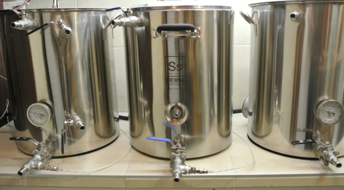
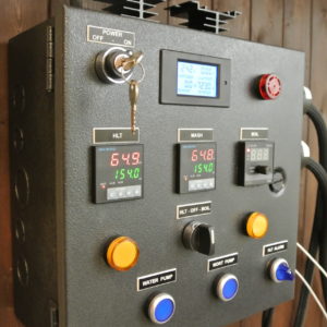
 I started like you… I was dreaming of going electric, having perfect control over temperature and process, and ultimately, making better beer.
I looked at different solutions and I decided that HERMS was the way to go for me. I was not afraid of a little plumping, or drilling a few holes in stainless steel, but there was still one obstacle; The Brewing Control Panel.
My electrical background was kind of limited and I was afraid that I could not get it done by myself. On the other hand, I was sure that I wouldn’t spend 1.5k on a control panel.
I did a lot of research and finally came up with a plan for my personalised control panel. If I can do it, you can do it!
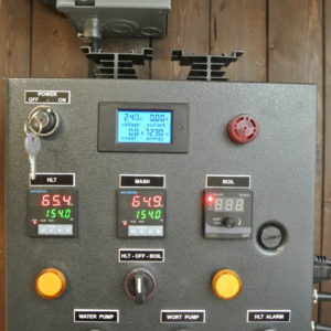
I built it with functionality, quality, security and cost in mind. It has everything needed in my opinion.
Download the complete guide for more detailed wiring instructions and everything else you’ll need to build an electric brewery.
Looking for a more affordable control panel? Check out my multipurpose AiONE controller.
What do people say about this tutorial…
I cant recommend this tutorial enough! It was my go to for building my electrical panel. Thanks for providing all the information you have.
Worth the $5 to me just to read it, even if I never fulfill my pipe dream of making a DIY 3-gal eBIAB system.
Excellent work! Very well written and photographed, thank you. I am sure this will help many people with their designs and builds.
Wow, it's really good work. Thanks for sharing, will be using this for my build.
Excellent! I just mounted my components in the exact same configuration (minus the voltage meter) and just haven't wired it up yet. Very clear now!
Excellent work and precise documentation! Thanks for the share.
Very helpful information, project done properly, thanks very much.
I built the system in October and have using it in the brewery as a pilot system...it has performed flawlessly!
A few words on security
The brewing control panel is controlling a high current/voltage brewing system. Be sure that you understand what you are doing and if you don’t, ask questions till you understand it!
A GFCI-protected source is mandatory if you want to live a long and happy life. You can use a GFCI breaker in your main electric panel, but a SPA panel with a GFCI breaker will most likely be cheaper.
Respect the mentioned wire gauges for the control panel and wires going to the heating elements.
Your kettles must be grounded correctly. I’ll show you below how to do that.
How it works
I won’t go into details about HERMS, you’ll find plenty of information on the web. This control panel is meant to be used with a 3 vessel HERMS system (HLT – Mash Tun – Boil Kettle) and is perfect for 5-10 gallon batches. Two pumps are used to move liquids.
The main switch, in combination with the main conductor, cuts power from the control panel.
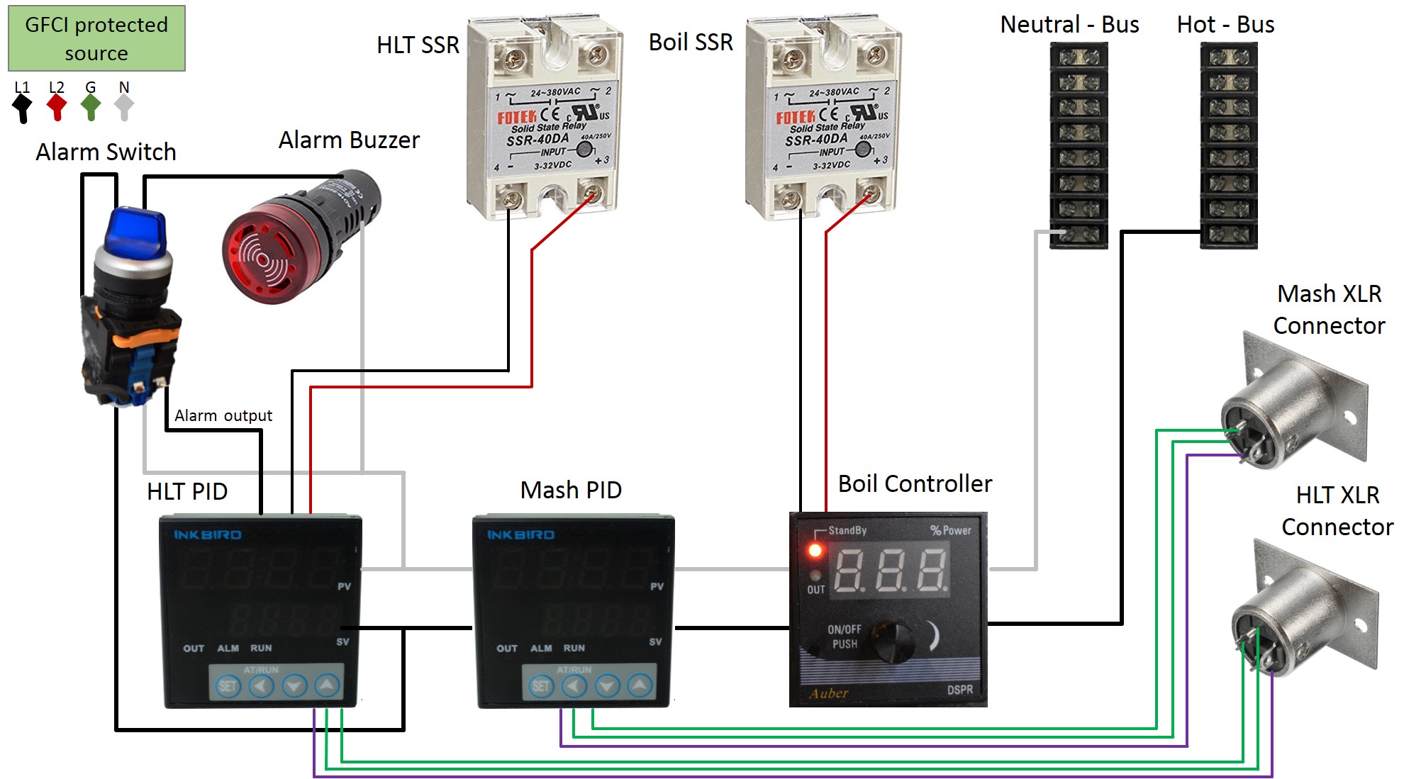
This control panel has 2 temperature controllers (PID’s) and one boil controller. The HLT PID is measuring the temperature of liquid circulating thru the HLT (RTD sensor) and is firing the HLT SSR, providing power to the 5500-watt element in the HLT. This PID will also trigger a buzzer when reaching the configured temperature, if we decide to set the alarm.
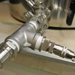
The mash PID is showing the temperature of the wort coming out of the mash tun (RTD sensor). This PID does not control an element nor anything else.
The boil controller is firing the boil SSR, providing power to the 5500-watt element in the boil kettle. The controller can be set from 0-100%.
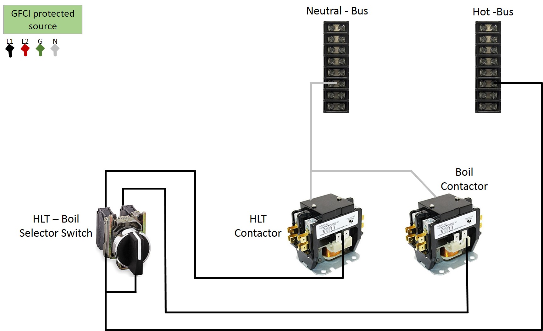
This system can only use one heating element at a time. LED indicators will show when a heating element is energized. When the element selector switch is in OFF position, no current is present on the HLT/Boil receptacles. Having the HLT/Boil contactor between the SSR’s and the outlets is improving security. SSR’s are tending to fail in a closed state, which would energize the heating element without the brewer’s consent.
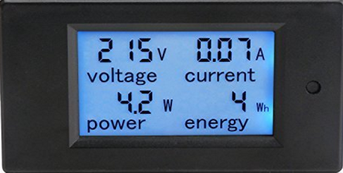
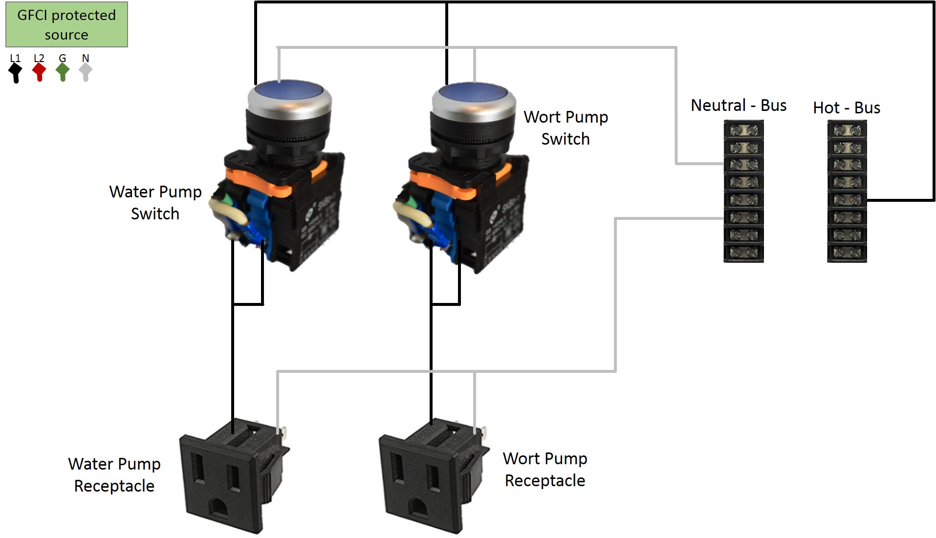
The two pumps are controlled by two switches with a LED indicator integrated. The AMP/Volt meter will show us what’s happening on the control panel. Its not a mandatory piece, but its useful to see how much current an element is drawing. It also replaces a ‘power on’ indicator as the display lights up when the control panel is on.
I refrained from integrating a timer on the control panel. A smart phone is much more convenient than a panel mounted timer can ever be.
Stuff you’ll need
You do not need to use the same components. Make sure that the parts have the correct current rating and the same functionality as the pieces mentioned below.
The box
I’ve used a Hoffman 12x12x6, sourced locally. The enclosure must have a ground post.
There is enough space inside this box. Before you cut your holes, make sure that all components will have space on the inside, not touching anything when closing the door.
Contactors
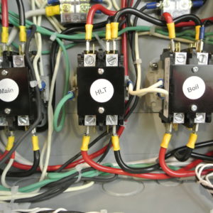
3 x 2 Pole 30 Amp Contactor 120 Volt Coil
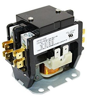
I’ve use Packard C230B 2 Pole 30 Amp Contactors, sourced from Amazon.
SSR’S
2 x 40AMP SSR’s + heat sink
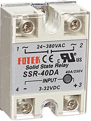
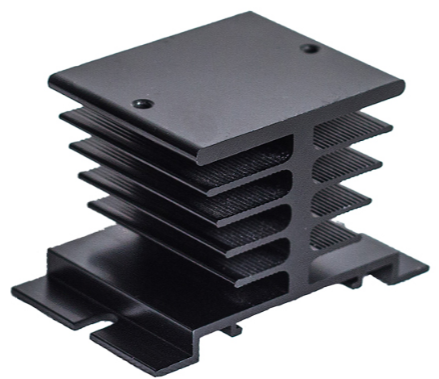
I’ve used 24-480V AC DC to 3-32VDC Output Single Phase SSR Solid State Relay 40A, sourced from Amazon.
Terminal Strips
2 x 8 position terminal strips, sourced from Amazon.

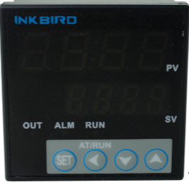
Mash / HLT PID
2 x Inkbird ITC-106VH, sourced from Amazon.
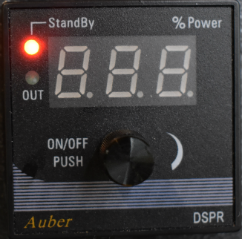
Boil controller
1 x Digital SSR Power Regulator for Wort Boiling Control DSPR1, sourced from auberins.com.
Volt/Amp meter
1 x DROK Digital Multimeter AC 80-260V 100A, sourced from Amazon.
Switches and Buzzer
1 x main switch
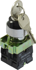
1 x alarm switch with integrated LED indicator
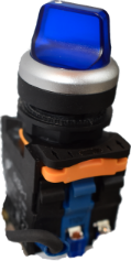
1 x 3 position selector switch
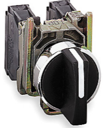
2 x push button switch integrated LED indicator
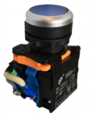
1 x buzzer with LED indicator
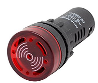
I’ve sourced all that (switches are rated to 10 AMP) from auberins.com.
LED indicators
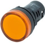
2 x 240V LED indicators, sourced from auberins.com.
Receptacles
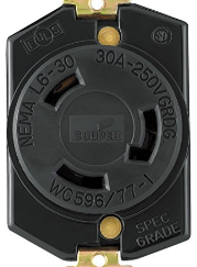
2 x Leviton 2620 30 Amp, 250 Volt, Flush Mounting Locking Receptacle, sourced from Amazon.
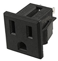
2 x 120V 15A US Socket, Panel Mount, NEMA 5-15R, sourced from auberins.com.
XLR connectors
2 x XLR 3Pin Male Panel Mount, sourced from Amazon.
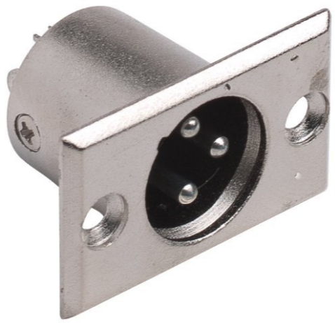
Fuse
1 x fuse holder with a 7 AMP fuse, sourced locally.
![]()
Wires and terminal connectors
You’ll need 10 AWG, 14 AWG and 22 AWG wires. Use standard wire and not solid core wire. It will be easier to work with and make a better connection with the terminal connectors.
You’ll also need terminal connectors, different sizes and shapes, tie wraps and self-adhesive tie mounts.
I’ve soured that locally.
Preparing the enclosure
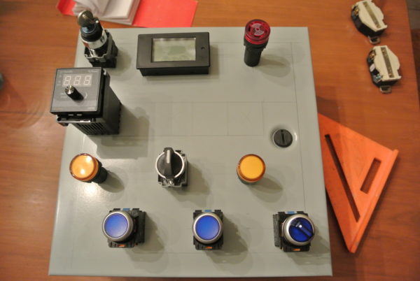
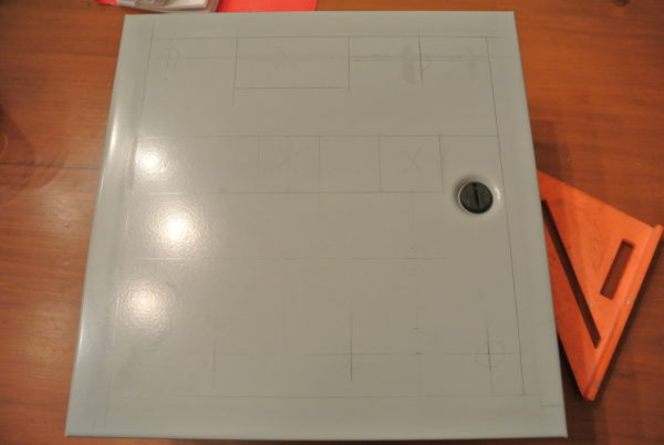
Start planning the position of each component on the control panel. Make sure that the components have enough space and that even after wiring, the door will open/close without issues.
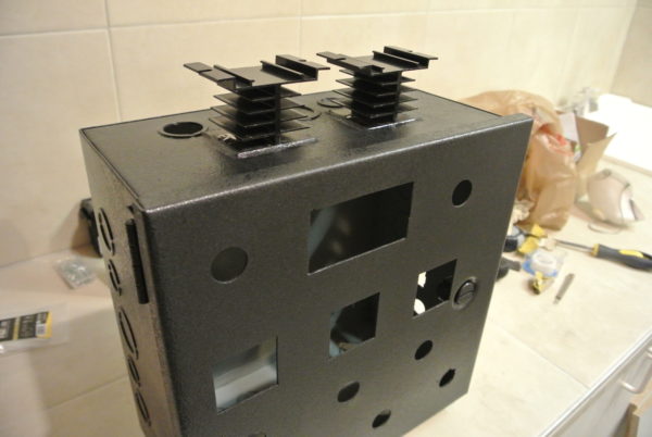
I’ve used a cheap step drill to make the round holes. You don’t need something fancy here. I’ve used the same step drill to make all holes in my SS kettles. The rectangular holes can be easily cut with a jigsaw. Just drill a hole and cut out the rest with a jigsaw (fine metal blade).
Use a metal file or sandpaper to smooth edges. Install all components to see if it fits.
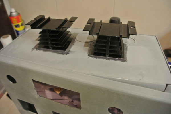
I’ve used JB Weld to attach the heat sinks on the top. Make sure that the SSR’s will fit thru the holes that you’ve cut on the top. The SSR’s need to have a nice contact with the heat sink. A thermal paste (Amazon) should be used.
It’s time to paint the enclosure if you like to do that. Don’t forget to sand and clean it truly before painting. I’ve used something like this (smells bad for days but works and looks great):

Once the paint dried, we are ready to install all electrical parts.
Wiring
Follow the steps below one after the other, carefully reviewing every step. Do some testing (multi-meter) after every step to ensure that everything is working correctly. Wire gauge must be matched! Use a crimp tool to attach terminal connectors. All connection must be tight, especially on the high current circuits. Loose connections can result in overheating and even fire.
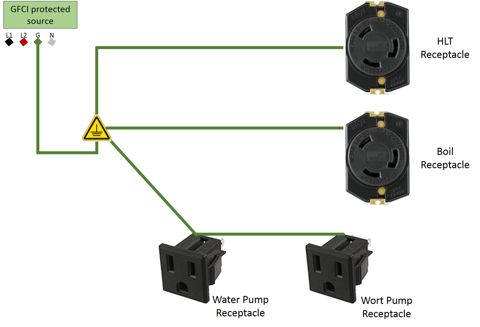
Grounding
We use 10 AWG to ground the receptacles and enclosure. I did not ground the door separately as my box has only one post, but it won’t hurt to ground the door too.
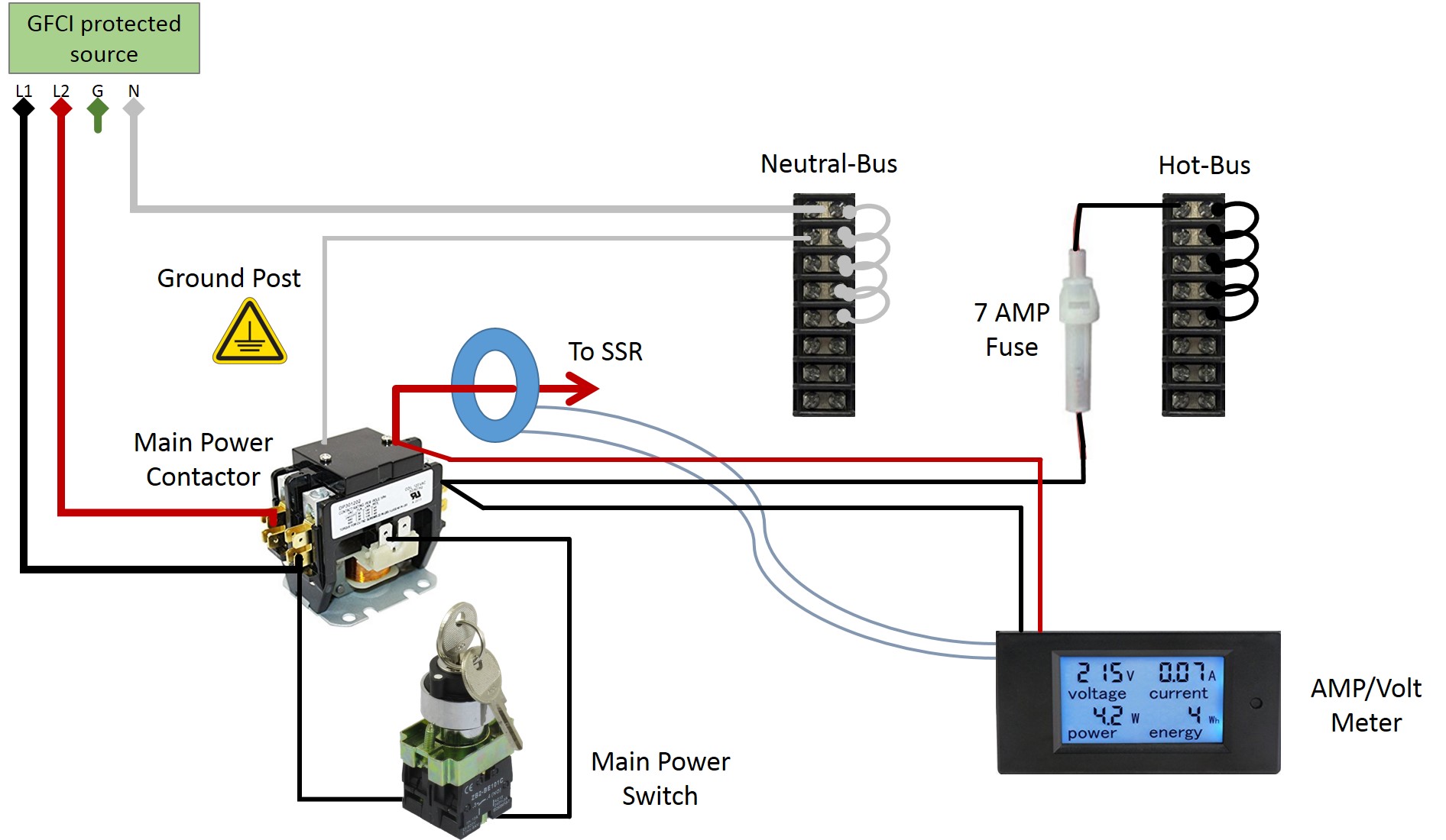
Main Power
The fat wires are 10 AWG and the smaller wires are 14 AWG. The fuse is used to protect the 14 AWG circuit. The 10 AWG wire is protected by the 30 Amp breaker in the main electric panel.
You can use short jumper cables to connect positions on the Hot and Neutral terminal strip.
240 volt circuit
The fat wires are 10 AWG and the smaller wires are 14 AWG.
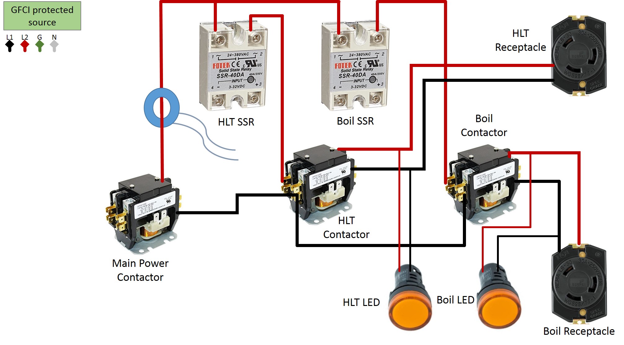
HLT / Boil element selector switch
14 AWG is used.
PID’s / Boil Controller
14 AWG is used, beside the wires going to SSR’s and XLR connectors, I’ve used 22 AWG for these connections. The wires to the XLR connectors are soldered. The alarm switch has a LED indicator integrated. The LED will be on when the switch is in ON position. The alarm buzzer will only be activated if the alarm switch is in ON position and the HLT PID is triggering an alarm. Wire the PID’s according the manufacturer instructions.
Pump Control
14 AWG is used. The push buttons have LED indicators integrated. The LED will be on when the switch is in ON position (pushed in).
Panel Tags
Tags are not that expensive and it will give your control panel a professional look.
I’ve sourced that from signsbannerstags.ca.
Heating Elements
2 x 5500-watts ULWD Elements
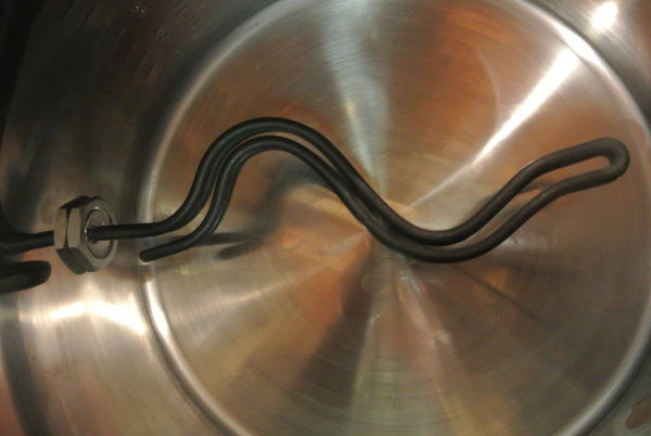
This is a very important part of your equipment. You want to use good quality elements. ‘Shiny’ does not mean better! It’s the opposite in general. Everything should be made of SS. I suggest to use Camco model 2965 ULWD elements.
You must install these elements in your HLT and boil kettle, creating a leak free seal.
There are many ways to do that and I will show you an easy, low cost option. You will get a leak free connection without fancy hardware.
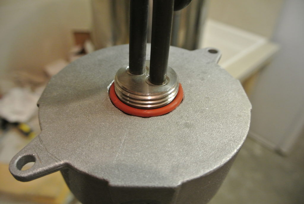
I’ve used a weatherproof outlet box.
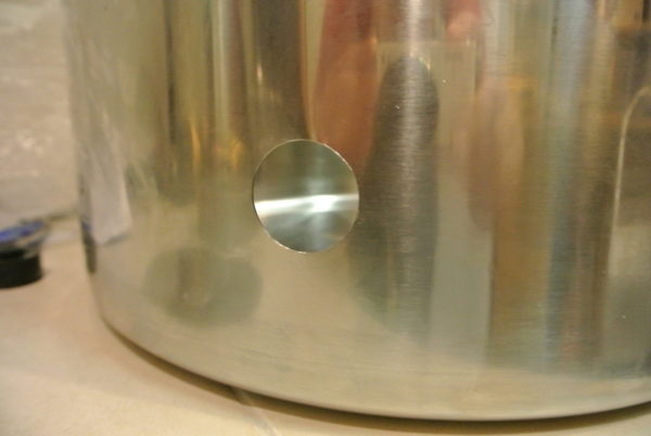
Use a step drill to drill a 1 ½” hole in the back of the box.
Install a silicon O-ring (1 3/16” ID X 1 7/1” OD) on the heating element. Insert the heating element into the hole in the electric box.
The O-ring must be thicker than the wall of the electric box. No extra metal washer should be needed here, if the box wall has the right thickness.
If not done, drill a 1 ¼” hole into you HLT and boil kettle.
Insert the element and attach it from the inside with a 1” heating element lock nut.
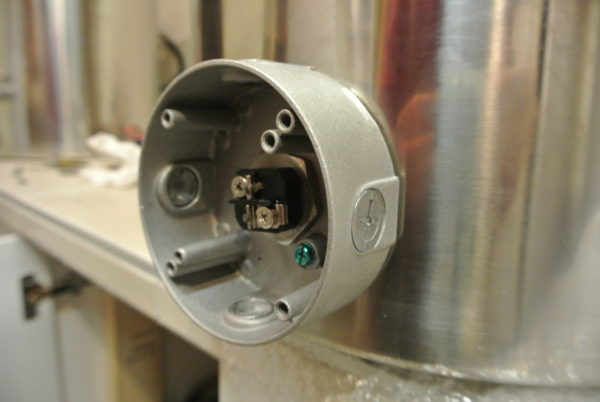
I have tightened that down till I could not turn the electric box by hand anymore. You can now fill the kettle with water to check for leaks. You should have a water tight connection and you should not be able to move the box by hand.
I’ve applied some food grade silicon on the inside. Just in case that the O-ring would leak one day, no liquid can enter the box.
You are now ready to connect the wires. Remember to use 10 AWG and a 30 AMP rated connector. Make sure to correctly attach the ground wire. Measure the resistance between your kettle and the ground post in the control panel. It should be close to 0.
Final Word
I hope this will inspire some folks to build their own brewing control panel / HERMS system. The process getting there can sometimes be overwhelming. Just take one step at the time and you’ll succeed.
I was mainly inspired by http://www.instructables.com/id/Electric-Brewery-Control-Panel-on-the-Cheap/.
Big thanks to jmengel for sharing his concept.
Feel free to ask if you have any questions. Feedback is always welcome!
Happy brewing!
