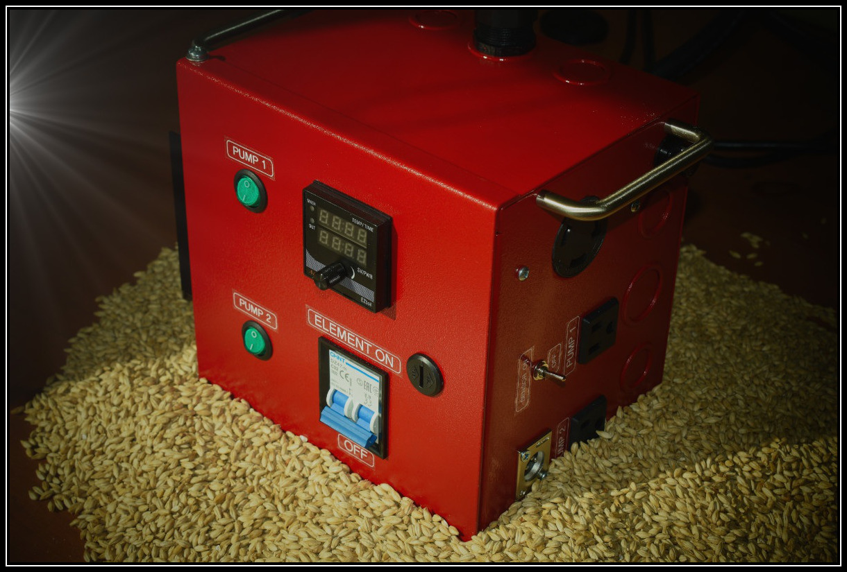
What is the AiONE Brewing Control Panel?
This control panel is a multipurpose brewing controller. It’s powered by 240V / 30 AMP and can run 2 pumps and a 5500-watt heating element. It has a mash/boil controller with integrated timer and buzzer.
If you want to build a bigger, dedicated HERMS control panel, check out my other tutorial.
A brewery controller that does it all. BIAB, RIMS, or even a full-scale HERMS, this controller will do it all.
- 240V / 30 Amp, enough power for brewing batches up to 20 gallons
- Very affordable
- Controls 1 heating element and up to 2 pumps
- Mash and Boil mode
- Integrated timer and buzzer
- Can be used with, or without a temperature sensor
- Built with safety in mind
- Easy to build
Why should you brew with electricity?
To me, brewing good beer boils down to 4 ingredients;
Creativity, Quality Ingredients, Process and Consistency. Refining any, or all of these components will most likely result in a better and more consistent product.
Brewing on an electric system won’t increase the quality of your ingredients and most likely it won’t help with your creativity. It will definitely allow you to improve your brewing process and certainly your consistency.
Brewing on an electric system has many advantages. I live in a very cold climate and I used to boil outside all year around. Temperature, humidity and wind affected boil off rates and boil strength. That was not only inconvenient, it directly affected my brew consistency.
I brew on E-HERMS, but this controller is designed to be used with any variation of electrical brewing system. You can use it as a single boil controller, control a RIMS or BIAB system and even control a full-scale E-HERMS setup.
There might be a few misconceptions, holding you back from building an electric brewery and I held back for the same reasons.
The price tag could be the first reason. While doing my research, I saw people spending 5K (and more) on building an E-HERMS brewery and I almost dropped the ball immediately.
I knew that I wanted to build with quality in mind, but I was far from willing to spend that much money on this project. The truth is that you can build it for much cheaper, using quality equipment and some common sense.
Another misconception could be that the equipment is difficult to clean and sterilize. I always thought that more equipment meant just more stuff to clean after your brew session. Already after my first brew day on my HERMS, I realized that it was much easier to clean than my old setup. Tubing is flushed, mash tun and boil kettle rinsed with hot water. Sterilizing is easy too. Hot wort is circulated through tubing, pumps and chiller.
Some also might not like the idea to mix fluids with electricity and I admit that I had the same concerns.
I know now that my fear was caused by the unknown and without any foundation. I will show you how to build a perfectly safe E-HERMS setup.
Download the complete guide for more detailed instructions, step by step brew day and everything else you’ll need to build an electric brewery.
A few words on security
The brewing control panel is controlling a high current/voltage brewing system. Be sure that you understand what you are doing and if you don’t, ask questions till you understand it!
A GFCI protected source is mandatory if you want to live a long and happy life. You can use a GFCI breaker in your main electric panel, but a SPA panel with GFCI breaker will most likely be cheaper.
Respect the mentioned wire gauges for the control panel and wires going to the heating elements.
Your kettles must be grounded correctly. I’ll show you below how to do that.
How it works
This control panel uses a single mash/boil controller (EZboil DSPR120), which is capable of managing the Mash- and the Boil- process. This mash/boil controller has a lot of options, like an integrated timer and buzzer which can be used during mash and boil. Please check out the user manual at auberins.com.
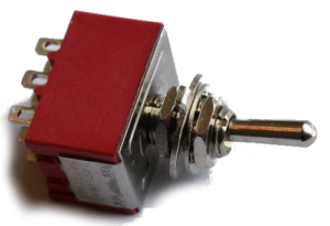
The DSPR120 will normally not work without a temperature sensor connected. This can be annoying if you are in boil mode, not using a sensor in the boil kettle. You might want to move stuff around for cleaning during boil and the sensor cable could be in your way. That’s why the control panel has a toggle switch on the side to bypass this restriction if needed. You can use the controller with, or without a sensor connected. If you don’t need this feature, just connect the sensor connector directly to the DSPR120, without using a toggle switch. If you want to use 2 sensors, you could also wire the toggle switch differently, so that you can change between two sensors (HLT, Boil kettle).
The mash/boil controller is measuring the temperature of water circulating through the HLT (RTD sensor) and is firing the SSR, providing power to the 5500-watt element in the HLT. It will hold the temperature at the desired value. The DSPR120 will also trigger a buzzer when reaching the configured temperature, if we decide to set the alarm.
The temperature of your mash tun will be very close to the HLT temperature, but you need to check the mash temperature and readjust the HLT temperature if needed.
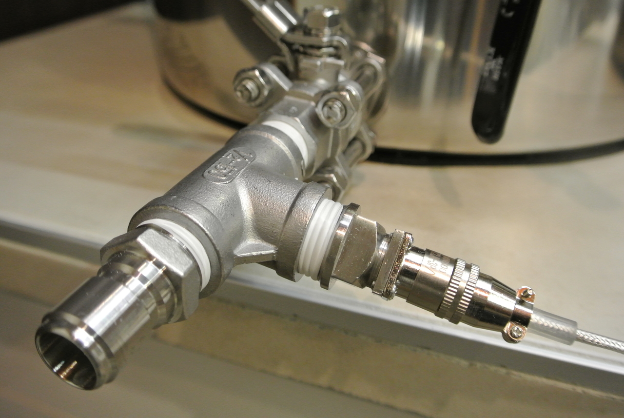
Your mash tun should have a thermometer. In theory, the HLT temperature should ultimately be identical with the mash tun temperature. That’s true but there is always a lag time when ramping up temperature and there might be a difference because of heat loss in tubing and pumps. That’s why you want to have a thermometer on the mash tun. An inline thermometer on the wort outlet would be the best choice.
When in boil mode, the controller can be set from 0-100% power.
Having a high voltage switch (breaker) between the SSR and the outlet is improving security. SSR’s are tending to fail in a closed state, which would energize the heating element without the brewer’s consent. Turn the element switch OFF when not heating!
There are 2 switches with integrated LED indicator and two 120V power outlets, to control pumps.
A fast blow fuse is protecting the 14 AWG circuit.


The Parts List
| QTY | Description | Sourced from | |
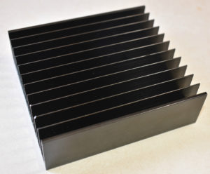 |
1 | Heat sink | auberins.com part # HS25ET |
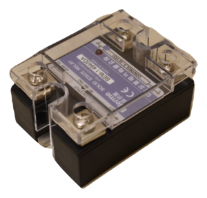 |
1 | SSR 40 AMP | auberins.com part # SRDA40 |
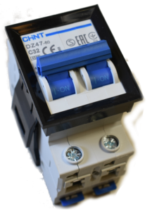 |
1 | High current switch 32 AMP | auberins.com part # SWM-DR-C |
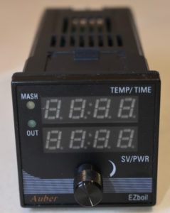 |
1 | Mash / Boil controller DSPR120 | auberins.com part # DSPR120 |
 |
1 | 9-PIN 3PDT ON/ON Toggle Switch | auberins.com part # TS3 |
 |
1 |
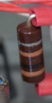
Resistor 100 Ohm, 1 watt |
|
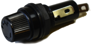 |
1 | Panel mounted fuse holder 15 AMP | auberins.com part # FSH-630 |
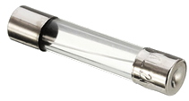 |
1 | Fuse (fast blow) between 7 – 10 AMP | Local car supplies |
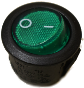 |
2 | Rocker Switch 120V 10A with LED | auberins.com part # KCD1 |
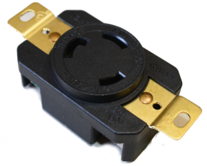 |
1 | 240V 30AMP Flush Mounting Locking Receptacle | auberins.com part # UC-L6-30R |
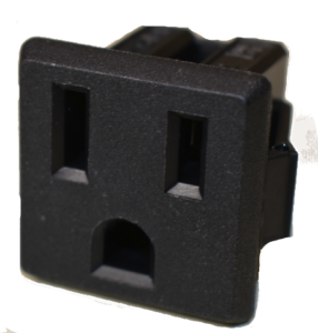 |
2 | 120V 15A US Socket, Panel Mount, NEMA 5-15R | auberins.com part # OUTS1 |
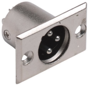 |
1 | XLR Connector for RTD Cable (Male Panel Mount). If you buy the Liquid tight RTD sensor form auberins.com, the XLR panel mount receptacles are included. | auberins.com part # XLRCON-M |
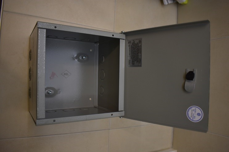 |
1 | Enclosure 8x8x6 | Local electric supplies |
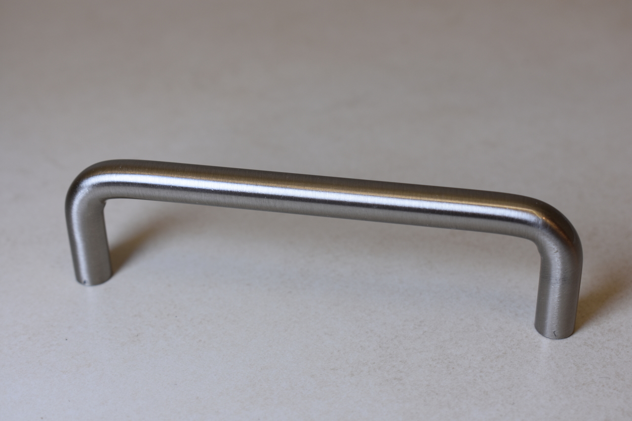 |
4 | Drawer pull | Hardware shop |
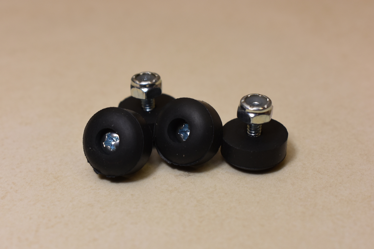 |
4 | Rubber legs | amazon.com |
| 2 ft | 10 AWG wire (stranded) – Red | Local electric supplies | |
| 2 ft | 10 AWG wire (stranded) – Black | Local electric supplies | |
| 6 in | 10 AWG wire (stranded) – Green | Local electric supplies | |
| 3.8 ft | 14 AWG wire (stranded) – White | Local electric supplies | |
| 8.5 ft | 14 AWG wire (stranded) – Black | Local electric supplies | |
| 16 in | 14 AWG wire (stranded) – Green | Local electric supplies | |
| 4 ft | 24 AWG wire – Red | Local electric supplies | |
| 3 ft | 24 AWG wire – White | Local electric supplies | |
| 1 | 10 AWG power supply cable (4 wires). You need about 1’ inside the box, the total length depends on where your power source is. | Local electric supplies | |
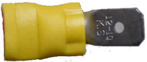 |
4 | Blade crimp terminal – male 10 AWG | Local electric supplies |
 |
1 | Blade crimp terminal – male 14 AWG | Local electric supplies |
 |
9 | Blade crimp terminal – female 14 AWG | Local electric supplies |
 |
5 | Blade crimp terminal – female 10 AWG | Local electric supplies |
 |
7 | Spade crimp terminal 10 AWG | Local electric supplies |
 |
2 | Spade crimp terminal 14 AWG | Local electric supplies |
 |
7 | Spade crimp terminal 24 AWG (small shape, must fit the mash/boil controller pin’s) | Local electric supplies |
 |
2 | Ring or spade crimp terminal 14 AWG (small shape, must fit the mash/boil controller pin’s) | Local electric supplies |
 |
2 | Straight crimp connectors 24 AWG | Local electric supplies |
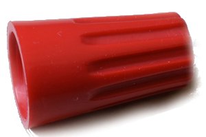 |
1 | Wire connector AWG 10 | Local electric supplies |
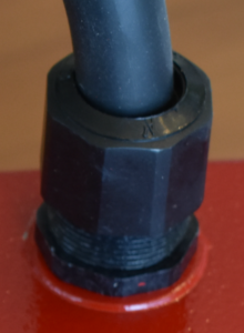 |
1 | Strain relief | Local electric supplies |
Preparing the enclosure
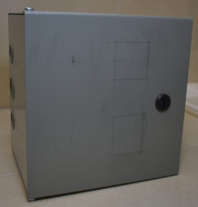
Start planning the position of each component on the control panel. Make sure that the components have enough space and that even after wiring, the door will open / close without issues.
Measure out the positions and use a pencil to mark the cut-out holes.
I used a step drill to make pilot holes for all rectangular shapes, then a jig saw was used to cut out the holes for the mash/boil controller, SSR, element switch and pump outlets.
All round holes can be perfectly drilled with the step drill. Use cutting oil and go slow (I used WD-40). The metal of the enclosure is usually smooth, easy to drill and cut. Some parts need to be attached with screws, just drill extra holes for that. Use a metal file or sandpaper to smooth edges.


Install all components to see if it fits.
It’s time to paint the enclosure if you like to do that. Don’t forget to sand and clean it truly before painting. I used spray paint.


Once the paint dried, we are ready to install all electrical parts.
Wiring
Follow the steps below one after the other, carefully reviewing every step. Do some testing (multi-meter) after every step to ensure that everything is working correctly. Wire gauge must be matched! Use a crimp tool to attach terminal connectors. All connection must be tight, especially on the high current circuits. Loose connections can result in overheating and even fire.
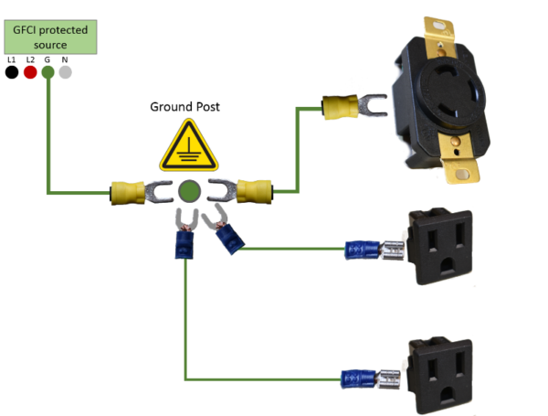
Grounding
The fat wires are 10 AWG and the thin wires are 14 AWG. I did not ground the door separately as my box has only one post, if your door has a 2nd post, ground the door too.
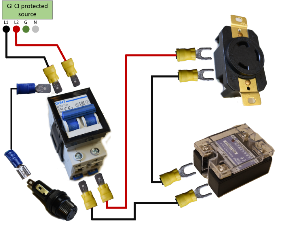
240 Volt Circuit
My control panel is directly connected to my SPA panel (GFCI). I don’t need to move my panel around, it made no sense to spend money on connectors and outlets. It’s important to place the SPA panel at a certain distance to your brew table, or any other water source. The electric codes can vary, depending on where you are, but normally it’s about 5 feet from a water source.
The fat wires are 10 AWG and the thin wire is 14 AWG. The fuse is used to protect the 14 AWG circuit. The 10 AWG wire is protected by the 30 AMP breaker in the main electrical panel.
Make sure to connect the SSR on the side where OUTPUT is marked.
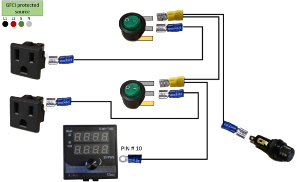
120 Volt Circuit – Hot
14 AWG wire is used.
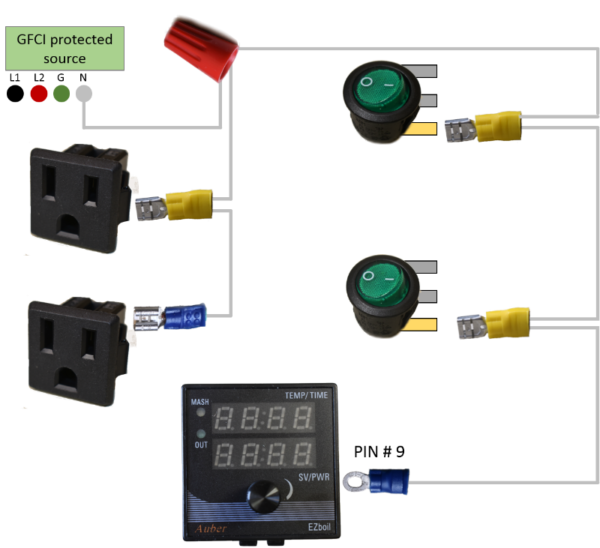
120 Volt Circuit – Neutral
14 AWG is used.
Brew Controller
24 AWG wire is used to control the SSR and for the connection to the XLR connector / switch.
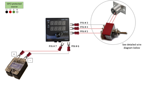
Detailed Sensor / Switch wiring
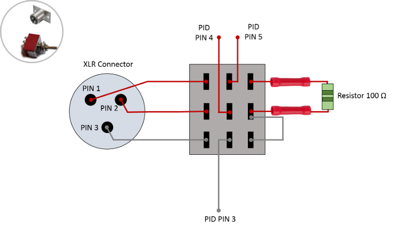
24 AWG wires are used. The connections are soldered, beside the resistor, which is connected with straight terminal connectors. Use solder flux and be careful with the solder iron, do not melt the plastic of the switch and XLR connector.


Panel Tags
Tags are not necessary, but it will give your control panel a professional look.
I used a label printer (BROTHER PTH110) with heavy duty tape.
You can also get panel tags on signsbannerstags.ca.
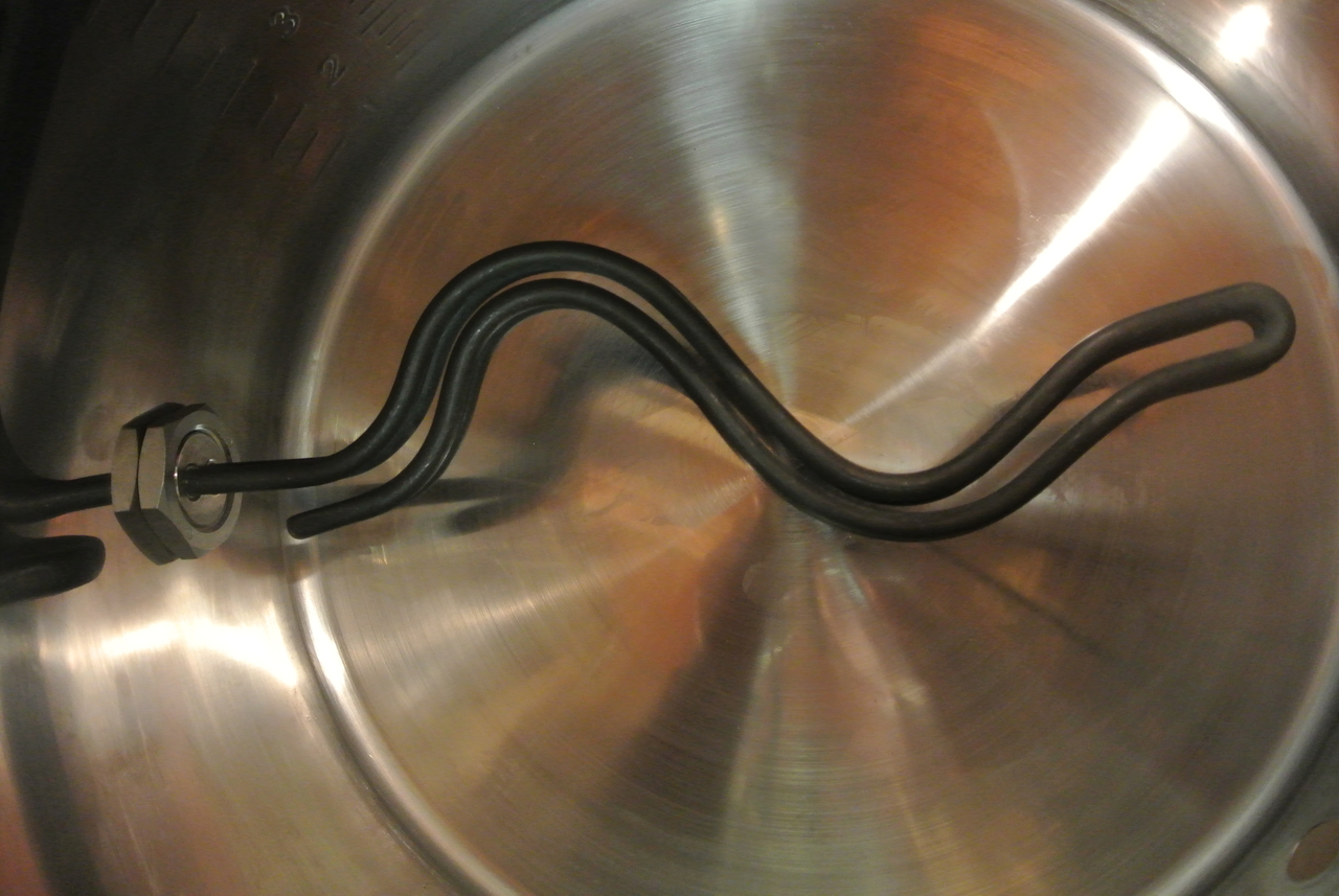
Heating Elements
2 x 5500-watts ULWD Element
This is a very important part of your equipment. You want to use good quality elements. ‘Shiny’ does not mean better! It’s the opposite in general. Everything should be made of SS. I suggest to use Camco model 2965 ULWD elements.
You must install these elements in your HLT and boil kettle, creating a leak free seal.
There are many ways to do that and I will show you an easy, low cost option. You will get a leak free connection without fancy hardware.
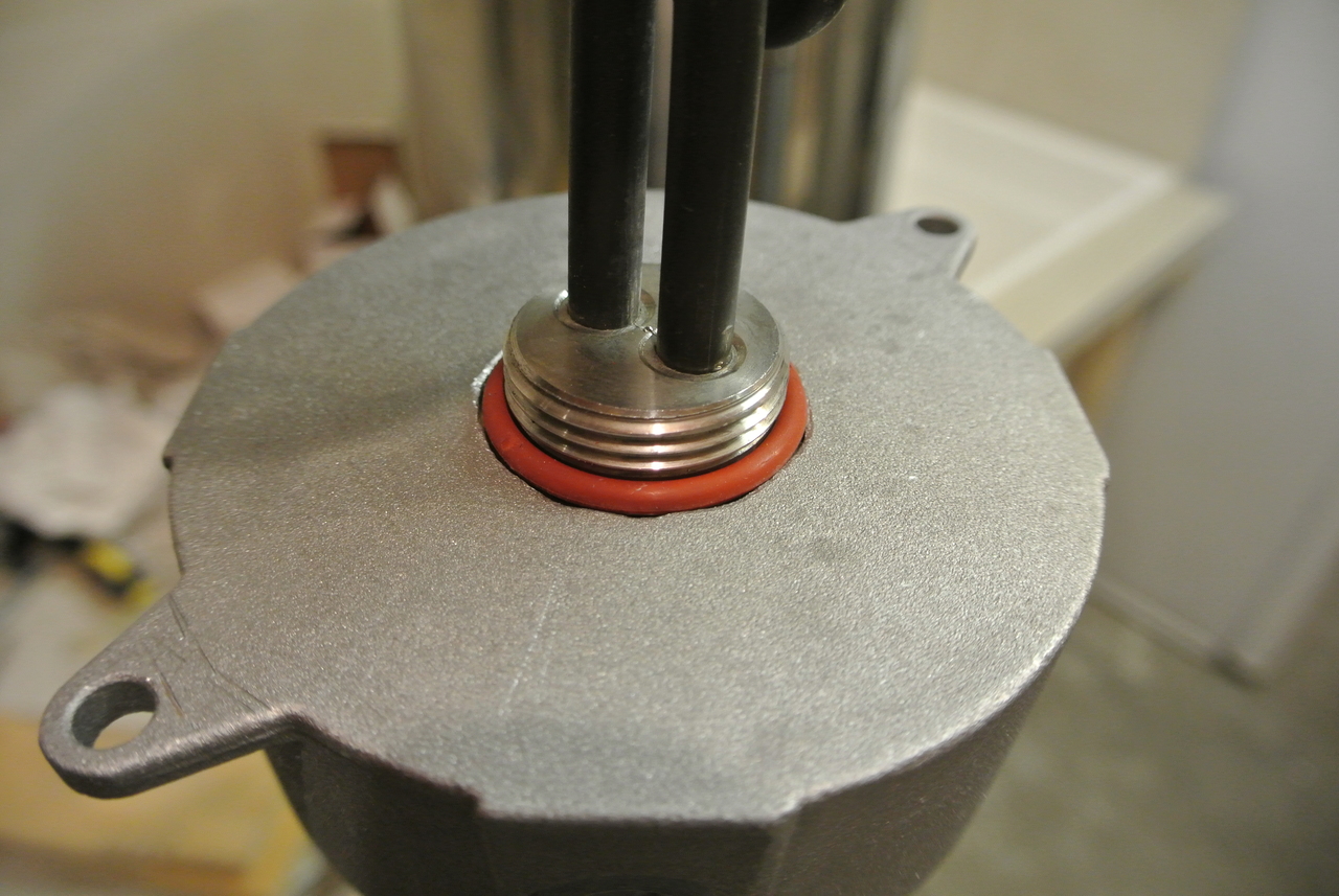
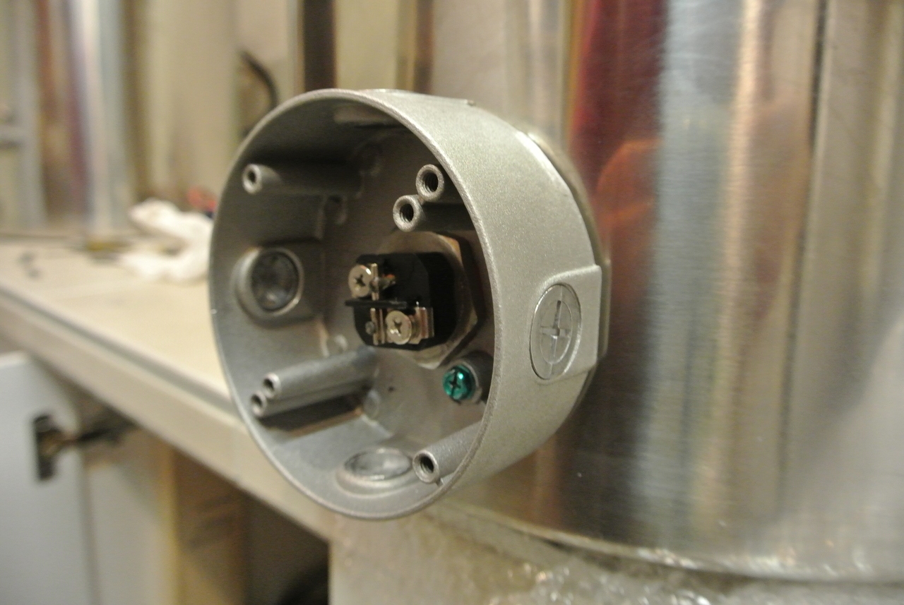
I’ve used a weatherproof outlet box.


Use a step drill to drill a 1 ½” hole in the back of the box.


Install a silicon O-ring (1 3/16” ID X 1 7/1” OD) on the heating element. Insert the heating element into the hole in the electric box.


The O-ring must be thicker than the wall of the electric box. No extra metal washer should be needed here, if the box wall has the right thickness.
If not done, drill a 1 ¼” hole into you HLT and boil kettle.
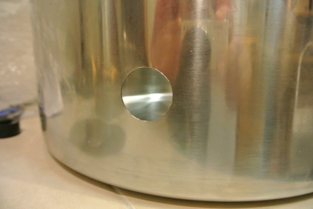
Insert the element and attach it from the inside with a 1” heating element lock nut.


I have tightened that down till I could not turn the electric box by hand anymore. You can now fill the kettle with water to check for leaks. You should have a water tight connection and you should not be able to move the box by hand.
I’ve applied some food grade silicon on the inside. Just in case that the O-ring would leak one day, no liquid can enter the box.
You are now ready to connect the wires. Remember to use 10 AWG and a 30 AMP rated connector. Make sure to correctly attach the ground wire. Measure the resistance between your kettle and the ground post in the control panel. It should be close to 0.


Final Word
I hope this will inspire some folks to build their own brewing control panel / HERMS system. The process getting there can sometimes be overwhelming. Just take one step at the time and you’ll succeed.
Feel free to ask if you have any questions. Feedback is always welcome!
Happy brewing!